After acquiring some aida and a set of fairly cheap embroidery silks, I decided to try my hand at cross-stitch. As with a lot of craft related activities cross-stitch and embroidery are having a resurgence. The fact that cross-stitch is essentially the first form of pixel-art makes it perfect for …
Articles tagged with Craft
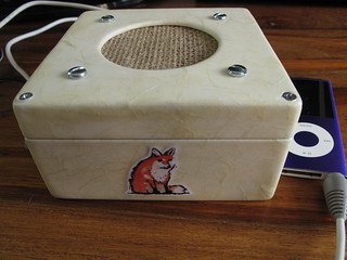
A small monobox speaker (LM386 amp + speaker in a box)
Fimo dinosaurs
I've been having a little Fimo renaissance lately. Partly due to using some Fimo for the nightlights I've made, but also from seeing some of the other wonderful things people like Joo Joo have made.
I saw a little guide on making photo stands out of plastic toy dinosaurs and …
Making a musical Robot Santa ornament using an ATtiny 85
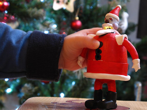
In what is threatening to become a tradition, I made a Christmas ornament again this year. Last year I just made simple tree ornaments using sculpey and fimo.
This year things got a bit more involved, as I decided to make a musical model of the Robot Santa from Futurama …
Arduino powered, temperature sensing, RGB LED nightlight
About a year ago I started on a project to make a temperature controlled nightlight. I was inspired by seeing these lovely LED lamps styled as mushrooms growing out of pieces of wood. Those mushrooms were made out of glass, which was somewhat beyond my skills. However I then saw …
Making a chair for a two year old
About a year ago I made a table for William's birthday. This year I decided to make him a chair to go with the table.
I learnt quite a bit making the table and that coupled with a few other projects (a raised bed and a small phone stand amongst …
Making a table for a one year old
So William is a year old now and to celebrate that fact I decided to make him a table. Now given that my last piece of woodwork was a doorbell, hastily constructed using a coping saw on the doorstep of the previous house, this could have gone badly. Luckily it …
"Ultimate" Arduino Doorbell - part 1 (Hardware)
After a first couple of small Arduino projects I felt the need to make something a bit more useful and permanent.
I had seen Roo Reynolds talking about hacking his doorbell to get it onto Twitter and as our doorbell is a bit rubbish I thought this seemed like a …
How to sew a felt horse
I've clearly picked up the making felt toys bug. For Christmas this year I ended up making a pair of felt horses for two of my cousin's children:
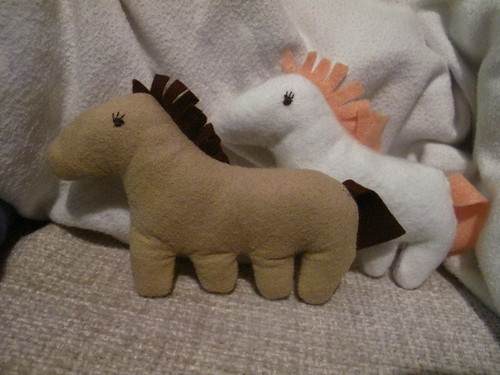
I thought I'd have a go at writing up the instructions for how I did this - complete with template for making your …
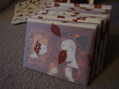
Two Months of Felt Creations
It's been a busy two months for me. I'll soon be getting married and there's been quite a lot to do. A while back I finished the invites for the wedding (which involved hand-stamped wrapping paper):
From there I moved on to creating a pair of robins to sit on …