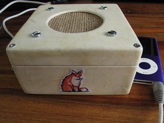
A small monobox speaker (LM386 amp + speaker in a box)

April 30th, 2013

I decided to have a go at making a monobox from the MAKE site. It’s basically a small battery (or mains) powered amplifier and mono speaker for playing music from an iPod/mp3 player. Here’s my finished monobox:

Monobox and iPod

The guide to make the monobox is pretty thorough and lists everything you need to get going. I used some slightly different parts in the end and the speaker was smaller than then one in the guide, but it still sounds good. The speaker itself was a 66mm mylar speaker from Maplin. I also used an extra 0.033µF capacitor instead of the 0.047µF too – which seemed to work ok.

At the heart of the circuit is an LM386 amplifier chip. Some of the Marshall practice amps use these chips, so you know they can’t sound too bad. The LM386 is designed for low-current/battery powered circuits, but obviously can still be used with a suitable mains adapter too.

The first job in building the circuit was setting it up on the breadboard:


Breadboarding monobox circuit

It sounded great when I first tested it out on the breadboard:


So with the circuit confirmed as working, the next step was to solder up the circuit and create a container for it & the speaker. I bought a small wooden box from Amazon to act as the case. I cut a circular hole in the box (using a fret saw and then Dremel to smooth the edges) for the speaker and cut out some pieces of plastic, foam and plywood to form a brace to hold the speaker in place:

Cutting out pieces for monobox

I then drilled some holes for bolts to mount the speaker inside the box:

Speaker fitted to lid of box
Inside view of speaker attached to box

After soldering the circuit up:

Close-up of monobox circuit

I tested the circuit out inside the box to make sure it sounded ok:

Testing speaker inside box
Speaker and circuit inside box

The hessian grill I’d attached was a little wonky at this point, but I decided to fix that later. There was a more pressing problem to deal with first.

A little stereo oddity

When testing out the circuit inside the box I went through quite a few different songs on the iPod. Most of them sounded good, but one in particular did not sound right. That song was “Space Oddity” by David Bowie. It sounded like you could only hear the backing track – the main vocal and other parts weren’t really there. Normally that’s what happens with a stereo when one speaker goes dead, but in this case there was only one speaker and it was meant to be receiving both sides of the audio. I experimented a bit and found that I could hear each side of the audio on it’s own ok. It was only when they were combined that it didn’t work properly. The weird thing was that most songs were ok, but not this one.

In the end I realised that it was due to how “Space Oddity” is mixed. Most songs nowadays seem to be fairly evenly spread out on both channels/speakers in stereo. “Space Oddity” on the other hand has one channel that is very quiet. This meant that the voltage coming out of that wire was normally very close to zero (at least compared to the other channel). The other channel’s voltage would be higher and by combining the two wires together there was effectively a short-circuit and some of the current would go back into the iPod rather than into the amplifier. So the answer to this problem was to properly combine the stereo channels to mono. This meant to putting two low value resistors (1.5Ω in my case) in before the channels meet. This creates just enough resistance to stop the partial short-circuit that was occurring.

Luckily I had left the speaker and power connections on the circuit board accessible via a female header, so I created a small “daughter” board with the resistors on:

Adding small board to mix stereo to mono for monobox

With the circuit finished and the stereo to mono mixing kink worked out I turned my attention to the box again.

Decoupage or so much sanding and varnishing

I opted to decoupage the box to give it a sort of antique look, which would also work well with the hessian speaker grill I was going to use. I first sanded down the box, filling in any holes etc with milliput (and sanding again). I then used a couple of coats of primer to seal the wood, the lightly sanded it all again, then spray painted it white:

Speaker box painted white

I then took some nice textured paper and stuck it all over the box using watered-down PVA glue. I also printed out a copy of a fox illustration I scanned in and stuck that on with PVA glue too. Then I started applying layers varnish. Luckily I chose to use quick drying varnish, which meant I only had to wait an hour between coats. I would paint on three layers of varnish, letting it dry between coats, then sand down with progressively finer sandpaper. I would then varnish again and repeat. I think in the end I must of applied about fifteen coats of varnish in the end (sanding about five times). Eventually the surface started to look pretty good when sanded, but there were still a few tiny shiny spots on the otherwise matt surface. To remedy that I used some matt varnish spray paint, which was just enough to even out the finish nicely:

Decoupage on the monobox box

With the box finished I glued the power and audio (3.5mm) connector in place:

Glued power and audio sockets into monobox
Power and audio sockets stuck in place

Re-gluing the speaker grill

Now that the box looked nice and well finished I decided I’d best re-glue the speaker glue to make it look neater. Previously I’d just stretched the hessian by hand before sticking it to a piece of plastic, but that left things looking a bit wonky and not very taut either. This time I used a large embroidery hoop to stretch the hessian first, then stuck the plastic to the hessian using two part epoxy:

Using embroidery hoop to pull hessian taut before gluing

Once the epoxy dried I cut out the plastic from the rest of the hessian:

Hessian speaker grill cut out

(NB. you can see the black foam seal here too)

Sealing the box

After I attached the circuit board with a small piece of wood and a screw to the inside of the box, I then needed to seal the box as best as possible. In case I needed to fix or adjust something inside the box I didn’t glue the box shut (as the original monobox guide suggested). Instead I hot-glued some felt around the inside to help stop sound escaping through the gap between lid and bottom:

Monobox circuit in place with felt seal

I then put in a bit of wadding to help further dampen any sound originating from inside the box:

Monobox filled with wadding

and then screwed the lid shut very tightly.

The finished monobox (complete with decoupaged fox illustration and hessian speaker grill)

A little buzz

The finished box sounds great, but when running off the mains there is a buzzing sound in the background. You can only notice the sound when you are close by and nothing is playing. It’s not enough to stop me using the monobox to play music, but it is annoying that it does it. My guess is that the power supply is adding in some extra noise. I did experiment with adding in some extra capacitors to smooth the power supply, but it didn’t seem to make a difference. When running off batteries there is no such buzzing sound and it should quite happily run off a 9V battery for about 24 hours or so.

Here you can see the finished monobox in action:


Fimo dinosaurs

March 29th, 2013

I’ve been having a little Fimo renaissance lately. Partly due to using some Fimo for the nightlights I’ve made, but also from seeing some of the other wonderful things people like Joo Joo have made.

I saw a little guide on making photo stands out of plastic toy dinosaurs and magnets and thought that I could do the same using Fimo. I ordered some tiny magnets online, that had a 300g pull – enough to be quite strong, but not so strong they’d cause any injuries! I also got hold of a few more varieties of Fimo and set to work:

The complete set of fimo magnet dinosaurs

From left to right, there’s an apatosaurus (green – aka brontosaurus), stegosaurus (yellow), tyrannosaurus (purple) and a triceratops (red).

You can see a better view here of the apatosaurus and triceratops holding the card, showing that they are made of two parts held together by the magnets:

Fimo dinosaurs holding a card

Each dinosaur was moulded from Fimo in one piece first. I then placed them in the fridge for a few hours to make the Fimo harder – so it wouldn’t deform when cutting. I then used a “tissue blade” (a very thin long blade) to cut the dinosaurs into halves before baking in the oven.

Fimo dinosaur halves Fimo triceratop halves

I then carefully out out holes for the magnets in each half – taking care to make sure the magnets were aligned correctly. Initially I used epoxy glue to glue the magnets in place, but later just opted for super glue, as it dries much quicker and was just as strong.

After the magnets were glued and the glue was dry I painted eyes, mouths and a few other features (e.g. yellow horns on the triceratops) with acrylic paint. I then used some matt varnish to protect the paint work.

I also made sure that the magnets were all aligned the same way so you could make mix’n'match dinosaurs, like an apatatops and a tricerasaurus:

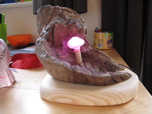
ATtiny85 RGB nightlight using Fimo and a piece of salvaged wood

February 28th, 2013

I recently created a second nightlight for my nephew’s first birthday. For this one I opted to use an ATtiny85 instead of an Arduino. As when I made the robot santa I used the Arduino environment for programming the ATtiny85 chip, as well as for prototyping the code.


Finished nightlight

For the main part of the nightlight I used a piece of wood I found in our front garden. I sawed the end off this, which had some really lovely knots in it and sanded it all off and cleaned up the awkward bits with a Dremel.


Wood for nightlight

I then varnished the wood and made a mushroom out of translucent Fimo with a RGB (three colour) LED embedded inside it.


Mushroom on nightlight glued in place

I also created holes for two buttons and stuck those in place. One button was the on/off switch, the other being used to change the colour of the LED.


Power and colour choice buttons glued onto nightlight

Then I soldered up the ATtiny with a power regulator (to convert the 9V power supply to 5V) a couple of capacitors (to help smooth out the power) and some resistors. I tested out the circuit connect to a breadboard with a switch, RGB LED etc before trying it out in the nightlight itself. The switch is connected to pin 0 of the ATtiny and ground (an pullup resistor is set to avoid needing a extra resistor in the circuit). The red, green and blue cathodes of the RGB LED are connected to pins 1, 2 and 3 of the ATtiny with current limiting resistors.


Innards of nightlight hooked up to breadboard

Testing all components glued in place work in nightlight

And that’s basically it. The code for the nightlight is here on github. The code runs a simple state machine to deal with button presses, fading the LED from one colour to the next and storing the colour chosen to EEPROM (so the colour is remembered for next time the light is turned on). There’s a little delay before writing to the EEPROM – in case the button gets pressed again. As EEPROM has a limited number of times it can be written to this seemed like a not so terrible idea. Hopefully though the EEPROM should still last for quite a long time anyway, as it’s rated for 100,000 writes before it fails.

Configuring an Edimax EW-7811UN on a Raspberry Pi for WiFi

January 27th, 2013

I was given a Raspberry Pi last year. I quickly got hold of an SD card, keyboard, mouse and a ten metre ethernet cable (to connect it to the router on the other side of the room). I installed the version of Raspbian released in July and set to work updating and installing software using apt-get. However whilst the Raspberry Pi seemed to be working fine, it appeared the the ten metre ethernet cable and/or my wireless router’s ethernet port weren’t so happy. Running sudo apt-get update took a long time. Running sudo apt-get upgrade to get to the latest version of the Raspbian kept timing out. Downloads speeds started fairly modestly (30-40Kb/s, quickly dropped to less than 1Kb/s and then gave out all together.

This was obviously somewhat frustrating. A big part of the appeal of the Raspberry Pi is that it connects to the internet. An ethernet should connection should work easily, but it appears that my router didn’t agree with that. Given that everything else in the house connects over WiFi it seemed like that was the route to take. It also meant I could lose the monster ethernet cable draped around the house.

So when I had a bit of free time again I got hold of an Edimax EW-7811UN Wireless Nano USB Adaptor and set about getting it working. It’s a really tiny little adapter, just barely larger the the USB plug itself. Which means that the Raspberry Pi can keep it’s diminutive form factor.

Of course though to get the adapter working I needed to upgrade to the latest version of Raspbian (which includes the WiFi drivers) – which in turn required a connection to the internet.

So to get a temporary network connection I connected the ethernet port on the Raspberry Pi to the ethernet port of of MacBook and turned on internet sharing to share the WiFi connection. This was great and I wish I’d thought of it sooner as it gave me a full speed connection (500Kb/s at least). Of course at this point I made sure the WiFi adapter was not plugged in.

So first job was upgrading everything using apt-get:

    sudo apt-get update
    sudo apt-get upgrade

That probably took about 20-30 minutes and included the drivers for the Edimax WiFi adapter.

I then rebooted the Raspberry Pi and plugged in the WiFi adapter. To see if the drivers were working I ran:

    sudo iwlist wlan0 scanning

Which listed all of the WiFi access points that could be seen by the adapter – which indicated that the adapter was working properly. The blue LED on the adapter also started flashing at this point.

The next job was to configure the adapter to connect using my WiFi network. I edited /etc/network/interfaces:

    sudo nano /etc/network/interfaces

And added the following to the end of the file (be careful here as you don’t want to mess up your network settings):

    auto wlan0
    iface wlan0 inet dhcp
    wpa-conf /etc/wpa.conf

That configures the wlan0 network interface to run and to use DHCP to automatically get a network address.

Next I had to add in the key and access point name (SSID) for the network:

    echo $(wpa_passphrase <ssid> <network password>) | sudo tee /etc/wpa.conf

The wpa_passphrase command is a handy way of generating the hexadecimal key that the configuration file wants (rather than the human readable password). I used sudo tee /etc/wpa.conf as simply redirecting the output directly to /etc/wpa.conf would not have enough permission otherwise.

This writes the settings on one line like this:

    network={ ssid="<ssid>" #psk="<network password>" psk=<long hex string> }

Which needs editing to break into more than one line (otherwise the # character will mess things up):

    sudo nano /etc/wpa.conf

The edited wpa.conf file ended up looking like:

    network={
    ssid="<ssid>"
    #psk="<network password>"
    psk=<long hex string>
    }

At this point that was all of the configuration done and it was time to fire up the wlan0 network interface (aka the WiFi adapter):

    sudo ifup wlan0

This thought about things for a bit (whilst it got a network address via DHCP) and then blue LED on the adapter lit up fully and I had a working WiFi connection!

Making a musical Robot Santa ornament using an ATtiny 85

December 29th, 2012

William tests robot santa

In what is threatening to become a tradition, I made a Christmas ornament again this year. Last year I just made simple tree ornaments using sculpey and fimo.

This year things got a bit more involved, as I decided to make a musical model of the Robot Santa from Futurama. It was a good thing I started working on it in November, as it took quite a few evenings to get it all finished.

The first seeds were planted when I read about using an ATtiny 85 to make a musical greeting card. What got me thinking was that so few parts were involved and it could all run quite happily off a three volt coin/watch battery. Farnell had ATtiny 85′s available for 89p each (when you ordered 10 or more). So the chips with a few parts wouldn’t cost too much at all.

The next step was figuring out how to program the ATtinys. There’s a really good series of tutorials on using an Arduino to program the ATtiny chips on the MIT high-low tech blog. I was using an older Arduino (Duemilanove) so the circuit was a little different – no capacitor on the reset pin. Instead there’s a 100 Ohm pullup resistor on the reset pin to stop the Arduino resetting when it’s used as a programmer for the ATtinys.

The MIT tutorial specified a fairly basic set of “cores” for the ATtinys. These are the extra files need to make the Arduino environment work (to a greater or lesser extent) on the ATtiny. The cores in the tutorial provided some of the basic functionality, but in the end I opted for Arduino Tiny cores. These added quite a lot of the functions from the Arduino environment. In particular they added the tone function, which would be very helpful when it came to playing music.

To just check that I could program the ATtiny chips I setup the programming circuit on a breadboard at first:

Programming Attiny85 using Arduino

Setting up the circuit each time quickly became boring though, so I got a proto shield and soldered up the circuit (plus headers) to make it easier to quickly get going:

Shield soldered for easy Attiny85 programming

At this point I went through a few blind turns with the code on the ATtiny, but as I was using the Arduino environment I could use the Arduino itself for writing the code. In particular I could then use the serial port to aid my debugging of what was going on. This helped a lot, as it turned out I’d not been allowing for the fact that int on the ATtiny/Arduino is only 16 bits in size – rather than the 32 bit you’d expect on most desktop computers. This meant I was accidentally going past the maximum size of the int (about 32,000) and getting odd (usually negative) numbers in the wrong place.

I found a great Instructable on making a working set of traffic lights out of an ATtiny and Duplo. This had a very simple interface, that just required pressing a momentary push button to turn on the lights, that would then put the ATtiny to sleep after a while. It was powered by a watch battery and when asleep would use a minuscule amount of power (a few micro-amps), so would still carry on running after several months asleep. This was great as the code showed me how to disable the analog to digital converter and the analog comparator, which really cut down on the power used. It also showed me how to enable an interrupt on pin 0 to wake the ATtiny from sleep when the button is pressed.

For the music I went for the simple approach of having a function that would simply loop through an array, calling tone, noTone and delay to play the relevant notes. It also turned on the LED whenever tone was called, so that it would light up in time to the music.

The note frequencies and beats were specified in an array stored in the PROGMEM section of the ATtiny chip. This is an 8Kb section of read-only storage, which means you can store more data in there than can fit on the 512 bytes of RAM of the chip itself. The only tricky part is you then have to read values out the PROGMEM section using functions like pgm_read_word_near – you can’t treat it like regular RAM. With a few C-macros the transcribed music looked this this:

#define BPM 100l
#define NOTES_LEN 46

prog_uint16_t notes[2*NOTES_LEN] PROGMEM = {
  /* bar 1 */
  NOTE_E3, BEAT,
  NOTE_E3, BEAT,
  NOTE_REST, HALF_BEAT,
  NOTE_A3, HALF_BEAT,
  NOTE_A3, HALF_BEAT,
  NOTE_REST, HALF_BEAT,
  ...

Each note used one 16bit value for the frequency and one 16bit number for the the beat length. The beat length could probably have been encoded in less space, but this just kept the code simple. Also I only used either whole beats (crochet) or half-beats (quaver), so there could have been further optimisation there. In fact the total transcribed music only use 92 bytes of space anyway, which would have easily fitted in the RAM of the chip, but it seemed like a good practice to store the data in this way.

With the code figured out I then went back to the hardware side of things. I took the top of a washing liquid bottle and made a small wooden frame to mount the electronics on. I then tested that a piezo buzzer could still be heard when placed inside the container, when it was being run off of a 3 volt watch battery (rather than the usual 5 volts provided by the Arduino):

Testing piezo in container

The circuit consists of:

Circuit diagram for xmas ornament

Next I cut out some perfboard to mount the components, soldered them in place and stuck the board using hot glue to the wooden frame:

Checking rough layout of circuit

Decoration soldered up

At this point the electronics side of the things was done. I finished transcribing the music for the ornament (the theme from Futurama), which you can just about hear:

At this point I have some electronics components stuck to a piece of wood shoved into a plastic container – not yet resembling Robot Santa. At this point it was time to break out the milliput and start adding some recognisable features:

Robot Santa takes shape

Robot Santa halves

Robot Santa assembled

The milliput took quite a while to add, as I added a part then had to allow it to dry before applying the next part. I probably ended up spending more on the milliput I used, than on the electronics.

After all the milliput was complete I painted Robot Santa using acrylic paint and added a coat of varnish.

Robot Santa painted and varnish drying

Robot santa deployed in front of the xmas tree

I had to drill some extra holes in the case so the Futurama theme was audible, though it’s still on the quiet side:

The code I wrote is available on github in my arduino sketches repo.

A quick Halloween Cylon Pumpkin using an Arduino and a few LEDs

November 1st, 2012

Back in 2006 the new Battlestar Galactica series was going strong (and was still rather good). So it was almost inevitable (in hindsight) that someone would make a Cylon pumpkin for Halloween. That pumpkin was featured in a Halloween copy of Make magazine I bought and then held on to for the next five years. Finally, five years later, I have made my own Cylon pumpkin:


The original used a 555 timer, 4017 counter, several capacitors, transistors etc. Which would mean a fair bit of soldering.

Seeing as I had an Arduino lying around and an Arduino can control six LEDs with PWM (pulse width modulation) in code this was something I could whip up quickly with a small child running around. So the first job was breaking out the breadboard, resistors, LEDs and Arduino to test the circuit out and write some code:

Arduino Larson scanner


That went pretty well and I then surprised myself by managing to solder the LEDs etc to make a simple “shield” for the Arduino. The LEDs were on a strip so they could be attached easily to the inside of the pumpkin.

Larson scanner soldered up and ready for pumpkin

Later in the week I carved the pumpkin:

Carving cylon pumpkin

Sadly though I didn’t take out enough of the flesh, so a couple of days later it “melted” and I had to throw it out. Luckily I’d been leaving it to dry out and so hadn’t installed the Arduino.

So I acquired another pumpkin and started again:

Extracting the pumpkin contents

This time I really made sure I removed as much flesh as I could (which contains a surprising amount of water) and it didn’t go squishy.

Finished mk 2 cylon pumpkin

I made sure I placed the Arduino inside a plastic tub to keep it off the inside of the pumpkin. Some bamboo skewers were used to hold the eyes/LEDs in place and stop the lid falling down:

Inside of cylon pumpkin

I also made a small hole at the rear of the pumpkin to feed the power supply for the Arduino in:

Back of cylon pumpkin

I’ve put the code and Fritzing diagram on github for anyone who wants to do something similar.

Building an Aerographics me163 (komet) free flight model plane

October 25th, 2012

When I was younger I built and flew a couple of radio-controlled (R/C) aeroplanes. These were made from kits and were of a fairly modern style, with foam core balsa-covered wings and covered with heat shrink plastic (attached using a small iron). The two planes I finished used small two stroke internal combustion engines running on glow fuel and had roughly 5′ wing spans. They were fairly sizeable. I found them a bit unnerving to fly as that propellor had quite a lot of force behind it and could easily of taken off a finger or more. I did get my licence to fly (which was mostly to meet the requirements for getting the 3rd party liability insurance the BMFA provided), but after a few crash/rebuilds I lost interest and moved on to other things. It also didn’t help that the nearest club was a fair drive away and I was too young to drive.

This marked the end of my youthful interest in aviation.

Like many children growing up in the 80′s aeroplanes were one of those things that you just seemed to know about. I knew far too many names and details about WW2 aircraft in particular. The TV always showed re-runs of Battle of Britain, 633 Squadron and The Dam Busters. Spitfire, Messerschmitt, Focke-Wulf, Hurricane, Mosquito, Lancaster, Heinkel were household names as far as I was concerned. Airfix kits were a regular fixture too.

I’d always wondered whether I’d get back into aeroplanes. Then when on holiday I happened on a model shop selling free flight balsa planes. I didn’t buy one then, but ended up going to the local model shop a few weeks later and came away with an
Aerographics M.e. 163 Komet kit:

Messerschmitt ME 163 Komet Kit

Much like the real ME 163 this kit could take a rocket motor. I opted to just make it a glider and would launch it with a bungee cord.

The Messerschmitt ME 163

In Wings of the Luftwaffe, allied test pilot Eric Brown talks about flying a captured ME 163. The German ground crew really didn’t want him to fly the plane. Apparently more ME 163 pilots died in accidents than in combat. The highly explosive two part liquid rocket fuel had a tendency to ignite and explode at the slightest provocation. In fact pilots had to ensure the fuel had been used up before attempting a landing – otherwise the slightest bump might ignite the remaining fuel and cause an uncontrolled explosion.

That said the ME 163 is one of those aircraft (like the ME 262 jet fighter and HO 229 flying wing jet bomber) from WW2 that looked like it belongs in some alternate World War 2 timeline. With it’s swept wing and tailless body it seems entirely alien to more “standard” aircraft of the period, such as the Spitfire and the Mustang. Luckily the aesthetics of the ME 163 weren’t a deciding factor in it’s effect on the war. It probably worked as something of a calling card for it’s designer Alexander Lippisch though, as he was later recruited as part of Operation Paperclip and went to the United States post-war.

The ME 163 was something of a last ditch attempt by the Third Reich to deal with the waves of Allied bombers. It’s fantastic rate of climb meant that it was potentially very useful for interception/point defence, but it was almost too fast and it’s guns were too slow, meaning it rarely scored much real damage on the enemy. That coupled with the explosive and accident prone rocket engine meant that it probably helped the Allies more than it hindered them.

Making the model

The ME 163 kit consisted of several sheets of 1/8″ balsa sheets with parts printed on (uncut), plenty of 1/8″ “stringers” and a few other asserted bits and pieces. The first job was therefore to cut out the required pieces from the balsa sheets. I started with the wing pieces:

Cutting out wing ribs for me163

Then pinned them into place on top of the provided plan (after covering the plan with cling film, to avoid glue sticking to the plan):

Constructing ME163 left wing

Constructing ME163 left wing

Constructing ME163 left wing

This was repeated for each wing, then the two wings halves were glued together – taking care to ensure that the wing tips were raised enough to add the right amount of dihedral:

Glueing the wings together

With the wing glued together the next job was the bottom of the fuselage:


Cutting out bottom pieces for me163 fuselage

Underside of me163 fuselage coming together

Underside of me163 fuselage

The bottom of the fuselage was then glued onto the wings:

Attaching underside of me163 fuselage to wings

With the top of the fuselage than built on top of the bottom and wings:

Top fuselage formers, top keel and fin fitted

Gluing stringers to top of me163 fuselage

Gluing stringers to top of me163 fuselage

Then I made a nosecone out of several pieces of thicker balsa shaped using my Dremel and added on the solid wing tips and it all started to really look like a proper plane:

Nosecone attached to me163

Then the whole plane was sanded lightly and some sanding sealer applied to the solid balsa parts (nosecone, tips etc):

Applying sanding sealer to me163

ME163 ready for covering

At this point all had gone pretty well. Then started the a potentially perilous next step – applying the tissue covering. First the wings:

Applying tissue to underside of me163 wings

Then the fuselage:

Applying tissue to fuselage of me163

Applying second section of tissue to underside of me163 fuselage

Nearly finished applying tissue to me163 fuselage

Correcting a bit of warp on me163 wing

After all the tissue was stuck in place I used a fine water spray to shrink the tissue slightly. Then I used cellulose dope on the tissue to further shrink the tissue and to make it stiffer:

Applying first coat of dope to me163

With the wings and fuselage covered in tissue and doped the next step was to add paper fillets to join the wings to the body properly. For this I used “bond” paper aka writing paper, which was then also doped:


Gluing paper fillets to wing and fuselage of me163

Paper fillets doped on me163

Then the plastic pilot was stuck together, painted with enamels and glued into place in the cockpit. I also had painted the inside of the cockpit by this stage:

Glued pilot into me163 cockpit

With the pilot in place the canopy was glued in place with epoxy resin:

Me163 canopy taped in place while glue dries

Masked canopy and painted outline on me163

With everything glued in place I made use of an airbrush and a 50/50 mix of cellulose thinners and enamel paints to paint the ME 163. This proved to be quite tricky, as the airbrush clogged quite easily and the cans of compressed air I used always seemed to run out too quickly. The finish did look very good though and I couldn’t have done the fuselage patterns any other way.

I think I should have got some low adhesive masking tape, as I ended up having to do some small repairs to the tissue on the wing when removing tape. I also made the mistake of not being able to exactly match the colour mixes I used. I could have mixed up larger batches and stored them until I was finished or used a straight out of the tin colour.

Light blue colour airbrushed onto me163

First shade of green applied to me163

Small rip from taking masking tape off wing

Nearly finished me163

Repainted repaired wing on me163

After airbrushing I applied the decals – using a little cellulose thinner to reduce silvering around the edges and the plane was looking pretty good:

Decals applied to me163

Underside of me163

Decals applied to me163

Less silvering around me163 decals

With the plane finished it was time to fly. After a fair bit of test throwing I bit the bullet and constructed a bungee + hook to fly the plane. This consisted of a “dog stake”, 10′ of bungee, 30′ of fishing line, carabiner, small key ring and wire hook.

Bungee instructions for me163

Bungee for me163

After finding a suitable nearby field I then tried out the bungee:

This showed that the plane need more forward weight, so I returned home to prepare for another flight.

Next time I taped a large number of fishing weights (nowadays tungsten instead of lead) to the nose before I tried again:

Fishing weights taped to noise of me163

A little better, but the ME 163 was still zooming up and high and stalling. This time this resulted in a fair bit of wing damage and repairs were needed:

Damaged wing on me163

Tissue cut off on me163 wings for repairs

me163 wing repairs

Sprayed water on tissue repairs to cause them to tighten

Repaired me163 just before 2nd crash

I also hollowed out the nose cone and added a small hatch so I could add more weight easily (and adjust in the field as needed):

Hatch on nose of me163

I skipped repainting before the next flight – which turned out to be a good thing:

me163 after crashing into tree

The final flight worked better than before – at least in terms of stalling etc. There was the slight issue of nearly losing the ME 163 after it hit a tree. I spent a good 15 minutes looking for it in the underbrush. I guess that’s the problem was painting a plane with camouflage.

At this point it seemed like retiring the ME 163 was a good idea. I had some moderately good flights and learnt a fair bit, but constantly having to rebuild would get boring quick. So it seems that the model ME 163 lived up to it’s real life counterpart’s reputation and crashed before it could engage in much real action.

So instead of rebuilding the crushed wing I have a Guillow’s P51 Mustand to build:

Guillow's P51D mustang kit

Unlike the ME 163 this is designed for rubber band power. The bungee cord used for the ME 163 exerted quite a force, which probably didn’t help prevent damage. I’m hoping rubber band power will be a bit gentler…

Arduino powered, temperature sensing, RGB LED nightlight

September 4th, 2012

About a year ago I started on a project to make a temperature controlled nightlight. I was inspired by seeing these lovely LED lamps styled as mushrooms growing out of pieces of wood. Those mushrooms were made out of glass, which was somewhat beyond my skills. However I then saw some had used translucent sculpey to make mushroom nightlights on instructables. So with that discovery it seemed like it would be rather simple to do…

The first job was to solder up a three colour (RGB) LED (a super bright one from oomlout):


Wires + RGB LED ready for coating in Fimo

I then covered the LED in translucent Fimo:


RGB LED and wires covered in Fimo

As Fimo only needs to be heated to about 100C to set it’s ok to do this, as it won’t hurt the LED. Also LEDs don’t normally give out much heat, so covering them is ok. Of course this is a relatively low power (though quite bright) LED as well which helps.

I found a branch on the way home from work, which I cut up and sanded down. This formed the base for the mushroom:


Testing fit of fimo covered RGB LED

As you can see I also opted for a chunky on/off button, in the style of the original mushroom lamps.

Next I put a small electronics project box into the bottom of the piece of wood and made space for a slide switch and power socket:


Power socket, slide switch and latch switch soldered

At the time I decided to try to use a Picaxe 08m chip to control the LED and read from a temperature sensor. The Picaxe 08m has a native function to read the temperature from a DS18B20 One Wire digital temperature sensor. It also had just about enough inputs and outputs to handle controller the three colors of the LED and reading from a slide switch (to make it switch between temperature display and plain nightlight). The individual chips were also pretty cheap, so it seemed like a good plan at the time.

However the size of the circuit and number of components I needed to solder was all a bit too much for me:


Red means fail

Eventually after much debugging I was able to get some things working – e.g. controlling the colour of the LED, but the temperature sensor just wouldn’t cooperate and always gave a high reading. I also managed to get through a few sensors due to mis-wiring them!

So I decided it was time to start again with the circuit. I bought a better soldering iron (a not too expensive digital temperature controlled one) and started on a new circuit:


Nightlight circuit take 2
Lots of jumper wires on nightlight circuit attempt 2

And before I could finish everything I lost impetus (an active toddler and a lack of sleep may have played a part) and the project sat on a shelf for nearly a year.

Then after discussing a friend’s Arduino experiments I realised that maybe I could use an Arduino Pro Mini to finish the job.


Comparing size of Arduino pro mini to original nightlight circuit

The Arduino was a lot more powerful than the Picaxe chip, with several K of RAM (vs. the 512 bytes for the 08m). Though it was overkill and cost more than the Picaxe chip it would make my life a lot easier. The Arduino gave me a 5V regulated power supply, so I could use the slightly simpler to read from TMP36 temperature sensor. I could also use internal an pullup resistor for the slide button. The other advantage to all that processing power was that I could use PWM (Pulse Width Modulation) when controlling the LED to produce a full range of colours. With the Picaxe I could only really have seven colours, with no smoothing between them. As this was intended to be used in the aforementioned toddlers bedroom having nice smooth transitions between colours was very appealing.

I soldered together the LED, switch, sensor etc to a small piece of perf-board with some female headers for mounting the Arduino too. I had to do a bit of work with a dremel to create more space, as the new setup was a bit taller too.

At this point I could then start programming the nightlight by hooking it up to a regular sized Arduino.


Nightlight working when wired to regular Arduino

This was great as it proved that everything was working fine and I could just focus on the code. It also meant I could do things like temporarily wire in a potentiometer instead of the temperature sensor, to make debugging the code simpler:


It was at this point that I then discovered what could have been a disastrous miscalculation – I spaced the headers for the Arduino Pro Mini too close together! Bit too much haste and perhaps a bit too little sleep, meant that I nearly had to start all over again for the fourth time! Luckily I found that as the headers were only 0.1″ closer together than they should be I could use some extra long male headers soldered on to the Arduino and bent to compensate:


Creating slightly offset headers for Arduino pro mini

Then it was a case of programming the Arduino Pro Mini using a serial adapter (carefully balanced so as to make contact correctly). I found I had to reset the Pro Mini and un-plug and re-plug the USB cable to get it work properly, but once the connection was good I could reprogram the board easily enough.


Programming Arduino pro mini with code for nightlight

All was good, so I decided to try out the nightlight by testing in different temperatures. The fridge seemed like a good starting point:


Testing nightlight in fridge

Luckily the weather was fairly warm that day too:


The nearly finished nightlight

I recorded a timelapse of the LED’s colour change as the temperature warmed up:


Changing color of nightlight after warming up from being put in fridge for a while

Sadly although the nightlight was responding to the change in temperature, it appeared that left to it’s own devices it would tend to warm up over a few minutes and then read a couple of degrees higher than it should. Without the bottom cover on it too longer to do this, so it was clearly some sort of a cooling issue, as it still read higher again if I turned the nightlight off then on again. I think I should have placed the sensor much further away from the rest of the electronics and made sure it was well ventilated.

So to help stop provide a little cooling/ventilation I ended up carving a wooden base our of pine, that I could drill a hole at an angle for cooling with an exit hole in towards the top of the main section. The base also gave the nightlight a bit more heft and made it easier to turn on/off as well as to operate the switch to change it from temperature to simple nightlight.


Wooden base for nightlight Nightlight on stand (rear view)

Despite the slight disappointment that the temperature reading wasn’t going to stay constantly useful, I am quite happy with the nightlight. It looks nice and will does work well as an actual nightlight. The temperature reading facility has been proving useful to see what the temperature of William’s room is like and therefore what sort of nightclothes would work best. Given how protracted it’s development has been I’m rather happy really. It’s also rekindled my respect for the Arduino platform. The Mini Pro in particular is great. It’s very small, but extremely powerful and as it’s a bit cheaper than a full size Arduino makes it more appealing for embedding it into a project permanently. I guess the only downside would be the lack of integrated USB connection (for serial IO), but that’s not needed for every project.


Nightlight on stand Nightlight on stand

As usual source code is available in my Arduino Sketches github repo (plus a Fritzing wiring diagram of the circuit).

DIY Canon G10 Camera Remote

August 27th, 2012

I quite enjoy some casual macro photography and am always taking pictures of various projects (which are usually on the smaller scale). For those types of photos you ideally need good light and a steady hand. When you don’t have good light then a tripod helps a lot, but a remote camera trigger is also useful. The main reason is so that you don’t shake the camera body when you press the shutter button.

After seeing a DIY guide to making a remote I thought I’d have a go at making my own. Most of the remotes I’d seen cost about £40. The parts I used to make my remote were only about £10. Of course it helped I already had a soldering iron etc…

The circuit is really simple, it just involves soldering a couple of push button switches to a 2.5mm stereo socket. Both switches connect to ground (the outer part of the socket). Each switch then connects to the other “side” of the socket.


Inside view of simple camera remote Inside view of simple camera remote

I mounted the switches (black for focus and red for shutter release) inside a small ABS plastic project box from Maplins. It’s quite a good size to hold in your hand and operate both switches with your thumb.


Camera remote for G10 (two switches) Camera remote for G10 (2.5mm socket)

I did also attempt to solder up the lead to go from the remote to the G10, but after a failed attempt I decided to order a lead via Amazon. The lead cost less than the unsoldered 2.5mm jacks cost.

So after a wait of a few days I got the lead and was very glad to find out that everything did indeed work as intended. I had made sure everything was connected right with my multimeter, but nothing beats trying something out in it’s intended use.


Camera remote hooked up to G10

So far this has probably been my most successful soldering/electronics project. Great to have something that simply worked straight away with no need to tweak anything.

Making a chair for a two year old

August 14th, 2012

About a year ago I made a table for William’s birthday. This year I decided to make him a chair to go with the table.

I learnt quite a bit making the table and that coupled with a few other projects (a raised bed and a small phone stand amongst others) meant that I was much more confident with my woodworking skills this time round.

When making the table the wood for the legs was maybe a bit thin for an amateur like myself and meant I had to use screws to hold everything together. This time I chose something a bit thicker, which would make creating “proper” joints much easier.

Pieces cut for chair

After brushing up on my chiselling technique I found making mortise and tenon joints pretty straightforward.

Mortise and tenon joint for chair

The great thing about using mortise and tenon joints was that I could then easily dry fit the pieces. At this stage it could even bear weight – though a knock from the side would cause it to fall apart again.

Testing fit of chair pieces

Next step was to create the base of the seat. This involved drilling holes in two pieces of wood, inserting dowels, gluing and clamping to make a wide enough single piece of wood. This was the same process I did when making the table, but I only needed to use two pieces of wood not four.

Gluing together two pieces of wood to form seat of chair

Then cut out the corners of the seat, made a small back for the chair and started to glue and clamp the frame pieces together.

All pieces cut out and now gluing and clamping chair

Lastly I drilled small holes into the bottom of the seat and top of the frame to insert dowels before gluing the seat in place.

Gluing and clamping seat of chair to body

With a couple of coats of varnish the chair looked pretty good.

Another coat of varnish applied to chair

The addition of a booster cushion made by Heather was the perfect finishing touch and a great second birthday present for William.

Finished chair and booster cushion