
In what is threatening to become a tradition, I made a Christmas ornament again this year. Last year I just made simple tree ornaments using sculpey and fimo.
This year things got a bit more involved, as I decided to make a musical model of the Robot Santa from Futurama. It was a good thing I started working on it in November, as it took quite a few evenings to get it all finished.
The first seeds were planted when I read about using an ATtiny 85 to make a musical greeting card. What got me thinking was that so few parts were involved and it could all run quite happily off a three volt coin/watch battery. Farnell had ATtiny 85's available for 89p each (when you ordered 10 or more). So the chips with a few parts wouldn't cost too much at all.
The next step was figuring out how to program the ATtinys. There's a really good series of tutorials on using an Arduino to program the ATtiny chips on the MIT high-low tech blog. I was using an older Arduino (Duemilanove) so the circuit was a little different - no capacitor on the reset pin. Instead there's a 100 Ohm pullup resistor on the reset pin to stop the Arduino resetting when it's used as a programmer for the ATtinys.
The MIT tutorial specified a fairly basic set of "cores" for the ATtinys. These are the extra files need to make the Arduino environment work (to a greater or lesser extent) on the ATtiny. The cores in the tutorial provided some of the basic functionality, but in the end I opted for Arduino Tiny cores. These added quite a lot of the functions from the Arduino environment. In particular they added the tone function, which would be very helpful when it came to playing music.
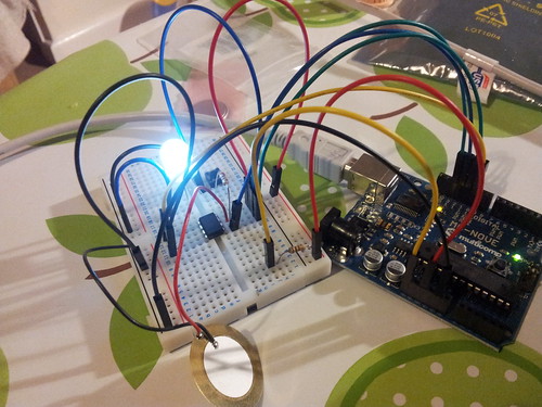
To just check that I could program the ATtiny chips I setup the programming circuit on a breadboard at first:
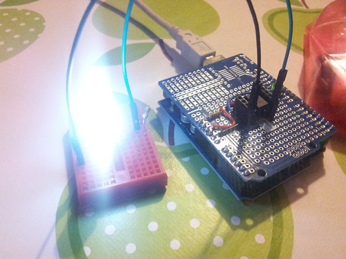
Setting up the circuit each time quickly became boring though, so I got a proto shield and soldered up the circuit (plus headers) to make it easier to quickly get going:
At this point I went through a few blind turns with the code on the ATtiny, but as I was using the Arduino environment I could use the Arduino itself for writing the code. In particular I could then use the serial port to aid my debugging of what was going on. This helped a lot, as it turned out I'd not been allowing for the fact that int on the ATtiny/Arduino is only 16 bits in size - rather than the 32 bit you'd expect on most desktop computers. This meant I was accidentally going past the maximum size of the int (about 32,000) and getting odd (usually negative) numbers in the wrong place.
I found a great Instructable on making a working set of traffic lights out of an ATtiny and Duplo. This had a very simple interface, that just required pressing a momentary push button to turn on the lights, that would then put the ATtiny to sleep after a while. It was powered by a watch battery and when asleep would use a minuscule amount of power (a few micro-amps), so would still carry on running after several months asleep. This was great as the code showed me how to disable the analog to digital converter and the analog comparator, which really cut down on the power used. It also showed me how to enable an interrupt on pin 0 to wake the ATtiny from sleep when the button is pressed.
For the music I went for the simple approach of having a function that would simply loop through an array, calling tone, noTone and delay to play the relevant notes. It also turned on the LED whenever tone was called, so that it would light up in time to the music.
The note frequencies and beats were specified in an array stored in the PROGMEM section of the ATtiny chip. This is an 8Kb section of read-only storage, which means you can store more data in there than can fit on the 512 bytes of RAM of the chip itself. The only tricky part is you then have to read values out the PROGMEM section using functions like pgm_read_word_near - you can't treat it like regular RAM. With a few C-macros the transcribed music looked this this:
#define BPM 100l
#define NOTES_LEN 46

prog_uint16_t notes[2*NOTES_LEN] PROGMEM = {
  /* bar 1 */
  NOTE_E3, BEAT,
  NOTE_E3, BEAT,
  NOTE_REST, HALF_BEAT,
  NOTE_A3, HALF_BEAT,
  NOTE_A3, HALF_BEAT,
  NOTE_REST, HALF_BEAT,
  ...
Each note used one 16bit value for the frequency and one 16bit number for the the beat length. The beat length could probably have been encoded in less space, but this just kept the code simple. Also I only used either whole beats (crochet) or half-beats (quaver), so there could have been further optimisation there. In fact the total transcribed music only use 92 bytes of space anyway, which would have easily fitted in the RAM of the chip, but it seemed like a good practice to store the data in this way.
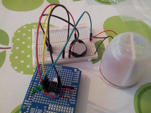
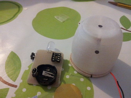
With the code figured out I then went back to the hardware side of things. I took the top of a washing liquid bottle and made a small wooden frame to mount the electronics on. I then tested that a piezo buzzer could still be heard when placed inside the container, when it was being run off of a 3 volt watch battery (rather than the usual 5 volts provided by the Arduino):
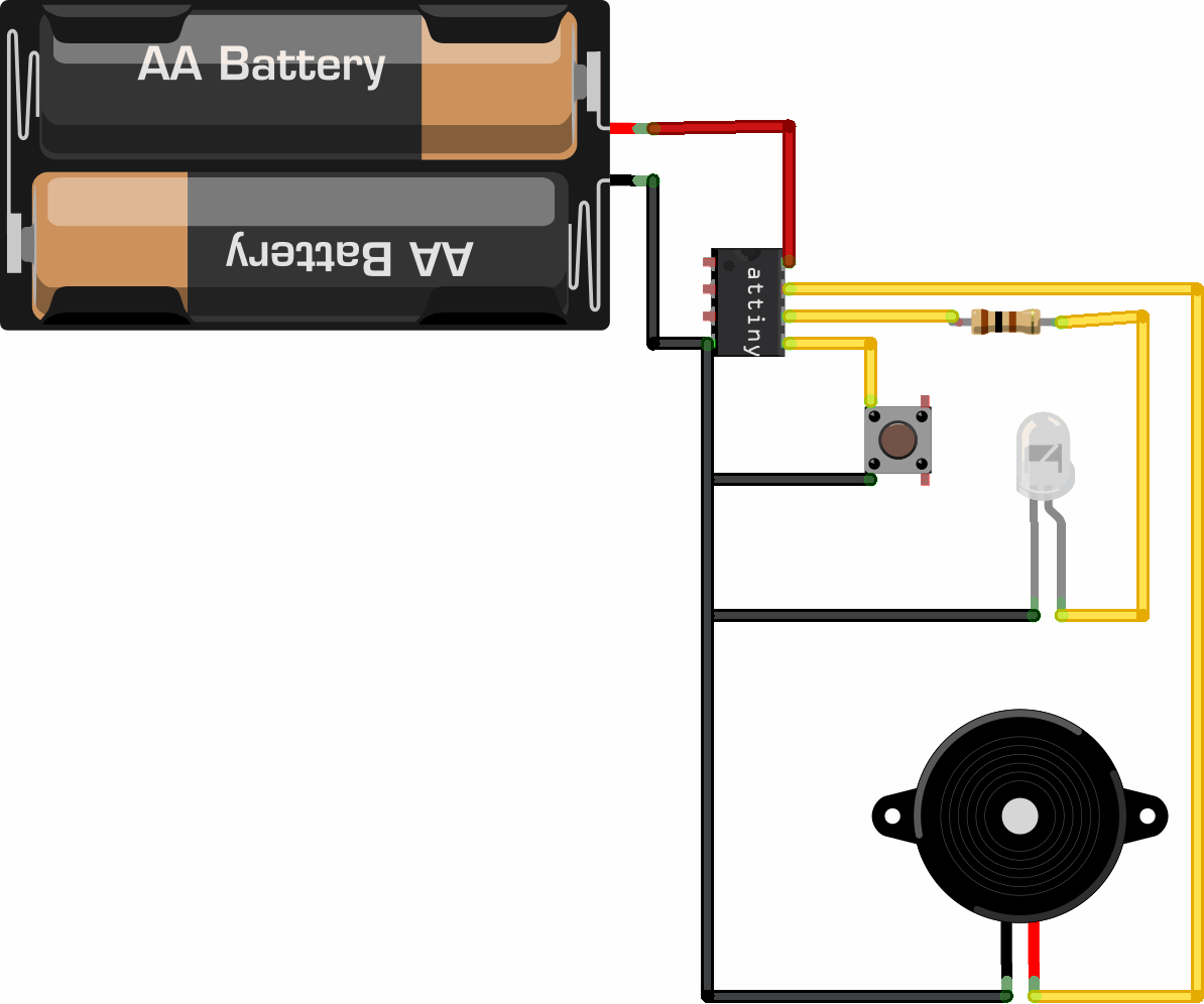
The circuit consists of:
- 3 volt battery holder
- Jumbo (1cm) LED (white)
- 100 Ohm current limiting resistor
- Small push button
- Piezo speaker/transducer
- 8 leg chip holder
- ATtiny 85
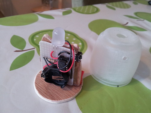
Next I cut out some perfboard to mount the components, soldered them in place and stuck the board using hot glue to the wooden frame:
At this point the electronics side of the things was done. I finished transcribing the music for the ornament (the theme from Futurama), which you can just about hear:
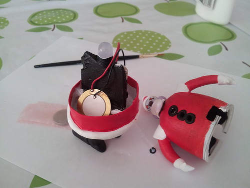
At this point I have some electronics components stuck to a piece of wood shoved into a plastic container - not yet resembling Robot Santa. At this point it was time to break out the milliput and start adding some recognisable features:

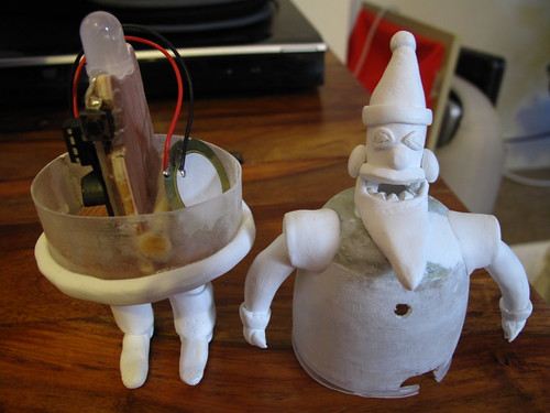
The milliput took quite a while to add, as I added a part then had to allow it to dry before applying the next part. I probably ended up spending more on the milliput I used, than on the electronics.
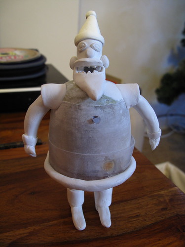
After all the milliput was complete I painted Robot Santa using acrylic paint and added a coat of varnish.

I had to drill some extra holes in the case so the Futurama theme was audible, though it's still on the quiet side:
The code I wrote is available on github in my arduino sketches repo.